
The past two weeks I have been working hard at getting the new MPLS WAN up and running. The idea is to build a scaleable solution, even though my MPLS cloud never will grow large enough to require the scalability. The plan is also to allow my colleagues to join the MPLS WAN, which means I need to think about locking down the WAN to keep them out of restricted parts of my provider core. 😛

This post will be devided into the following parts:
- DMVPN WAN
- LDP – thanks, but no thanks
- InterAS Option 10B 2a
- Verifying VPNv4 reachability
Here is an overview of what we are aiming to build:
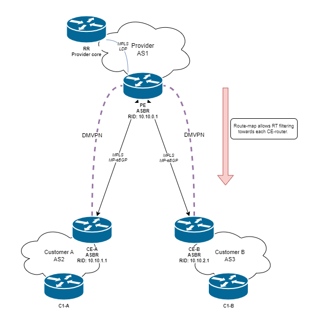
1. DMVPN WAN
DMVPN will be used to provide secure reachability across the internet, where the PE-router is the NHS. Of course we will run IKEv2 for negotiating the tunnels.
Here is an example of the PE-router DMVPN interface configuration:
interface Tunnel0
 description MPLS-o-DMVPN
 ip address 10.0.0.1 255.255.255.240
 no ip redirects
 ip mtu 1380
 ip nhrp map multicast dynamic
 ip nhrp network-id 1
 ip nhrp holdtime 450
 ip tcp adjust-mss 1360
 tunnel source GigabitEthernet0/0/0
 tunnel mode gre multipoint
 tunnel key 1
 tunnel vrf wan
 tunnel protection ipsec profile IPSEC_PROFILE
Here is an example of a CE-router DMVPN interface configuration:
interface Tunnel0
 description MPLS-o-DMVPN;link-to-provider
 ip address 10.0.0.3 255.255.255.240
 no ip redirects
 ip mtu 1380
 ip nhrp network-id 1
 ip nhrp holdtime 120
 ip nhrp nhs dynamic nbma 1.1.1.1 multicast
 ip nhrp shortcut
 ip tcp adjust-mss 1360
 tunnel source GigabitEthernet0/0/0
 tunnel mode gre multipoint
 tunnel key 1
 tunnel vrf wan
 tunnel protection ipsec profile IPSEC_PROFILE
DMVPN – Done!
2. LDP – thanks, but no thanks
For the interconnect we will be running InterAS Option 10B 2a (Next-hop-self). This means we will not be running LDP between the ASBRs, but rather MP-eBGP will handle the label distribution.
3. InterAS Option 10B 2a
Now we are getting to the good stuff! First of all, we want to create a extended community list which will be used to indicate which VPNs should be transmitted to each peer. The extcom list will then be applied to the MP-eBGP peering using a route-map. Here is the PE configuration:
ip extcommunity-list standard CE_A_ALLOWED_RT permit rt 1:101
ip extcommunity-list standard CE_A_ALLOWED_RT permit rt 1:102

route-map CE_A_RM_OUT permit 10
 match extcommunity CE_A_ALLOWED_RT
route-map CE_A_RM_IN permit 10
 match extcommunity CE_A_ALLOWED_RT


ip extcommunity-list standard CE_B_ALLOWED_RT permit rt 1:201

route-map CE_B_RM_OUT permit 10
 match extcommunity CE_B_ALLOWED_RT
route-map CE_B_RM_IN permit 10
 match extcommunity CE_B_ALLOWED_RT
This will allow the L3VPNs using the route-targets of 1:101 and 1:102 respectively to traverse the interAS connection. For connections where we are not the owner of both ASBR-routers it is paramount to restrict which route-targets are allowed.
Next up is the interface configuration, which is the same on both the ASBRs. Here we are going to enable MPLS traffic on the DMVPN interface, which will allow the tunnel-interface to send and receive labeled traffic.
interface Tunnel0
 mpls bgp forwarding
We can verify that the interface is enabled for MPLS labeled traffic by running the following command on each ASBR:
CE-A#show mpls interfaces
Interface              IP            Tunnel   BGP Static Operational
Tunnel0                No            No       Yes No     Yes
Now to the BGP configuration. Here is where the configuration between the Provider ASBR and the Customer ASBR will be slightly different. We will be using the next-hop-method to allow forwarding between the provider LSP and the MP-eBGP interconnect.
Here is the Provider ASBR:
router bgp 1
 bgp log-neighbor-changes
 bgp graceful-restart
 no bgp default ipv4-unicast
 no bgp default route-target filter
 ! AS1 Route-reflector
 neighbor 172.16.0.1 remote-as 1
 neighbor 172.16.0.1 update-source Loopback0
 ! CE-A
 neighbor 10.0.0.3 remote-as 2
 neighbor 10.0.0.3 update-source Tunnel0
 ! CE-B

 neighbor 10.0.0.4 remote-as 3
 neighbor 10.0.0.4 update-source Tunnel0
 !
 address-family ipv4
  neighbor 172.16.0.1 activate
 exit-address-family

 !
 address-family vpnv4
  ! AS1 Route-reflector
  neighbor 172.16.0.1 activate
  neighbor 172.16.0.1 send-community both
  neighbor 172.16.0.1 next-hop-self

  ! CE-A
  neighbor 10.0.0.3 activate
  neighbor 10.0.0.3 send-community both
  neighbor 10.0.0.3 route-map CE_A_RM_IN in
  neighbor 10.0.0.3 route-map CE_A_RM_OUT out
  ! CE-B
  neighbor 10.0.0.4 activate
  neighbor 10.0.0.4 send-community both
  neighbor 10.0.0.4 route-map CE_B_RM_IN in
  neighbor 10.0.0.4 route-map CE_B_RM_OUT out
And here is the corresponding configuration for a Customer router:
router bgp 2
 bgp log-neighbor-changes
 no bgp default ipv4-unicast
 no bgp default route-target filter
 neighbor 10.0.0.1 remote-as 1
 neighbor 10.0.0.1 update-source Tunnel0
 !
 address-family vpnv4
  neighbor 10.0.0.1 activate
  neighbor 10.0.0.1 send-community both
 exit-address-family
4. Verifying VPNv4 reachability
We can start by verifying the neighbourship between the ASBRs:
PE#show ip bgp vpnv4 all sum
[...]

Neighbor        V           AS MsgRcvd MsgSent   TblVer  InQ OutQ Up/Down  State/PfxRcd
10.0.0.3    4        2    5851    5964      736    0    0 3d16h           2
After that we can create the three VRFs which we will be sent to the customers: VRF101, VRF102 and VRF201. Here is the PE-router configuration:
vrf definition 101
 description mgmt
 rd 1:101
 route-target export 1:101
 route-target export 2:101
 route-target import 1:101
 route-target import 2:101
 !
 address-family ipv4
 exit-address-family
!
!
interface Loopback101
 vrf forwarding 101
 ip address 169.254.101.1 255.255.255.255
!
router bgp 1
 !
 address-family ipv4 vrf 101
  redistribute connected
 exit-address-family
!

vrf definition 102
 description mgmt
 rd 1:102
 route-target export 1:102
 route-target export 2:102
 route-target import 1:102
 route-target import 2:102
 !
 address-family ipv4
 exit-address-family
!
!
interface Loopback102
 vrf forwarding 102
 ip address 169.254.102.1 255.255.255.255
!
router bgp 1
 !
 address-family ipv4 vrf 102
  redistribute connected
 exit-address-family
!

vrf definition 201
 description mgmt
 rd 1:201
 route-target export 1:201
 route-target export 3:201
 route-target import 1:201
 route-target import 3:201
 !
 address-family ipv4
 exit-address-family
!
!
interface Loopback201
 vrf forwarding 201
 ip address 169.254.201.1 255.255.255.255
!
router bgp 1
 !
 address-family ipv4 vrf 201
  redistribute connected
 exit-address-family
!
And here is the CE-router of customer A:
vrf definition 101
 description mgmt
 rd 2:101
 route-target export 1:101
 route-target export 2:101
 route-target import 1:101
 route-target import 2:101
 !
 address-family ipv4
 exit-address-family
!
!
interface Loopback101
 vrf forwarding 101
 ip address 169.254.101.2 255.255.255.255
!
router bgp 2
 !
 address-family ipv4 vrf 101
  redistribute connected
 exit-address-family
!

vrf definition 102
 description mgmt
 rd 2:102
 route-target export 1:102
 route-target export 2:102
 route-target import 1:102
 route-target import 2:102
 !
 address-family ipv4
 exit-address-family
!
!
interface Loopback102
 vrf forwarding 102
 ip address 169.254.102.2 255.255.255.255
!
router bgp 2
 !
 address-family ipv4 vrf 102
  redistribute connected
 exit-address-family
!
This should create the new VRFs on the routers and allow us to ping across the ASBR interconnect, within the VRFs.
On the PE-router run:
PE#ping vrf 50 169.254.101.2 source 169.254.101.1
Type escape sequence to abort.
Sending 5, 100-byte ICMP Echos to 169.254.101.2, timeout is 2 seconds:
Packet sent with a source address of 169.254.101.1
!!!!!
Success rate is 100 percent (5/5), round-trip min/avg/max = 14/14/16 ms
You can also ping from the Provider RR to verify that the LSP -> MP-eBGP forwarding works correctly, but this won’t be described here.
That should be all of it! Now I can bask in the wannabe SP glory that is MPLS in the homelab.
I want to give some credit to sources which helped me set this up:
Leave a Reply