When growing up I used to do a lot of stuff with electronics. Back then, mostly basic stuff, integrating different SoC’s or IC’s that are already pre-made. I also did do a fair bit of micro-controller work, mostly with the Arduino ATMega chips.
Recently, I have been itching to get another project started, and what else than to do some electronics surrounding radio communications. I also wanted an opportunity to “produce” a product - that is, I want to build something that is a bit more polished that the perfboard creations of my past. That includes CNC milled housings and custom PCB boards.
So, my very ambitious project is to try and develop a Multi PTT device which allows some modularity. I would love it to use a modular connector, which would allow be to adapt this same PTT system to different radios. I also want it to support two radios, currently Hytera radios, but in the future, also other radios from other vendors.
I am also very inspired by the Disco32 products, which seem to have some great features, even though I currently have no idea how to emulate the dynamic “sensing” system inside that device. So, I think for my first version it should be fine with a simple circuit that allows two Hytera radios to be connected to the same PTT and then that PTT to be connected to a single-lead pair of Peltor Comtacs.
The second step of the development would ideally be to provide some sort of amplification. The Hytera + Comtac combo actually does require an amplified PTT (at least from the limited information I can find online). The Comtac impedance is 150 Ω, which is considered low-impedance, thus requiring amplification.
A cool note though, is that I have been running the Comtacs with an unamplified PTT now, and the Hytera radio handles in OK. I did have to adjust the “External Mic Gain” of the Profile inside the Hytera software. The default Gain setting is 20dB for the “External Mic Gain”, but I bumped it up to the maximum value of 30dB.
Now, while this works OK, it just about only works OK. Some of the words are heard clear, while others are not really. The Hytera also has Noise Cancelling, which I think might be causing some issues with the low impedance microphone. So in short, I would like to try amplifying the microphone signal before the Hytera radio.
The third step might be that we make the wiring dynamic, similar to how Disco32 does it. This is probably the most challenging goal, since it will have to 1) detect if the device is NATO or PELTOR/CIV wired, and 2) detect if the microphone is a low- or high-impedance. Ideally I would want to do this without a microcontroller, but we will see when we get there.
Analyzing the 13 pin connector
One of the first steps is to analyze the 13 pin connector that allows us to interface with the radio.
After digging through some documentation online I managed to find the following two tables:
13 pin pinout
| Pin number | Name | Function | Interface type |
|---|---|---|---|
| 1 | SPK+ | External speaker + | Analog speaker output |
| 2 | SPK- | External speaker - | Analog speaker output |
| 3 | MIC+ | Differential input of external microphone + | Analog mic input |
| 4 | MIC- | Differential input of external microphone - | Analog mic input |
| 5 | SWB+ | Power supply output of accessory interface | DC output from radio battery (nominal 7,7V) |
| 6 | GND | Ground | Common ground |
| 7 | SEL1_OPT | Accessory identifier 1 | Digital input.Default: pull-up (10kΩ connected to 3,3V inside radio) measured 3,283V to GND.Activate: pull-down to GND (pin 6). |
| 8 | SEL2_OPT | Accessory identifier 2 | Digital input.Default: pull-up (10kΩ connected to 3,3V inside radio) measured 3,281V to GND.Activate: pull-down to GND (pin 6). |
| 9 | SEL3_OPT/1_WIRE | Accessory identifier 3 or 1-wire communication port | Digital input.Default: pull-up (1kΩ connected to 3,3V inside radio) measured 3,295V to GND.Activate: pull-down to GND (pin 6). |
| 10 | PTT | Push To Talk | Digital input.Default: pull-up (10kΩ connected to 3,3V inside radio) measured 3,281V to GND.Activate: pull-down to GND (pin 6). |
| 11 | TK | TK programmable key | Digital input.Default: pull-up (15kΩ connected to 3,3V inside radio) measured 3,267V to GND.Activate: pull-down to GND (pin 6). |
| 12 | USB+ | USB+/RXD | USB |
| 13 | USB- | USB-/TXD | USB |
13 pin selector options
| Number | SEL1_OPT | SEL2_OPT | SEL3_OPT | SWB Powered | Description |
|---|---|---|---|---|---|
| 3 | Low | High | Low | Yes | USB primary mode for the radio. |
| 4 | Low | High | High | Yes | Conventional earpieces. |
| 5 | High | Low | Low | Yes | USB slave mode for the radio. |
| 6 | High | Low | High | Yes | Conventional remote speaker microphone. |
| 7 | High | High | Low | Yes | Serial programming cable. |
| 8 | High | High | High | No | No accessory connected. |
Since we will be building a PTT (which will then connect to an earpiece), we should connect pin 7 (SEL1_OPT) to pin 6 (GND), while leaving the pin 8 and 9 disconnected on the 13 pin accessory port. This will classify the accessory as a number 4 “Conventional earpiece”
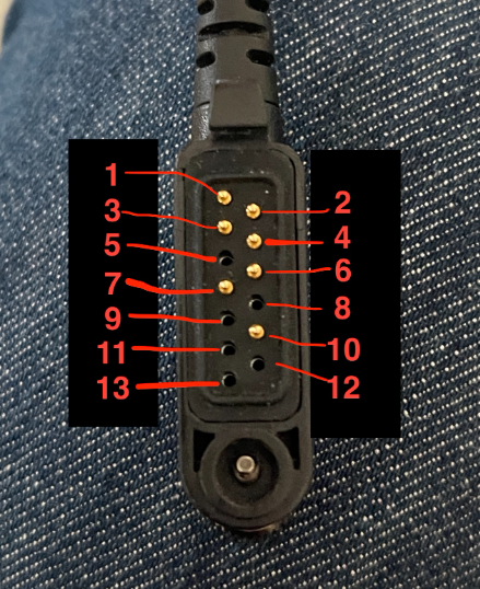
Here is a picture of the pins on a accessory connector by the way:
I also sketched up how the pins are connected inside of the radio. NOTE! These are estimations based on measurements, educated guesses and schematics. Do with my guesses what you will.
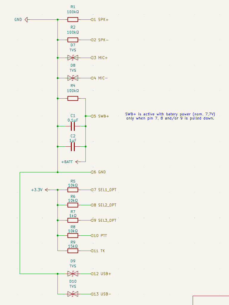
There are still a lot of things that are unknown, that I will need to figure out. Some of those things are the input voltages and current of the microphone input.