Ok so following my last port I have done a bit more research and work on the electronics. I have figured out that I should split the circuit into the following main parts:
- Power - Pull power from SWB on radio, or maybe if this does not work then from a battery.
- Speaker mixer - A OpAmp based inverting mixer will be used to mix all sound sources feeding into the headset.
- Microphone amplifier - Also inverting OpAmp circuit.
- Peltor/Nato wiring - A circuit that can swap between Peltor and Nato wiring.
- Impedance detection - Ie. should the microphone amplifier circuit be used or bypassed.
However, I also began the work on modeling the 13-pin connector in CAD.
The 13-pin model
So, since I do not have access to any actual drawings of the accessory port, I have had to manually draw this myself. The first step was to disassemble a working accessory connector:
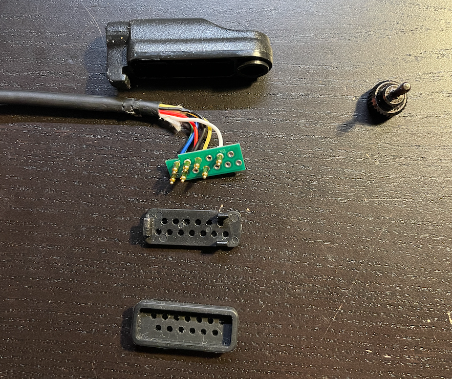
The connector can be broken into five main parts:
- Housing
- Circuit board
- Plate
- Gasket
- Thumb screw
These then are assembled into the 13-pin connector.
Housing
The housing is really just a plastic container for all of the components. I have begun modeling the housing in CAD already, and this is my progress thus far:
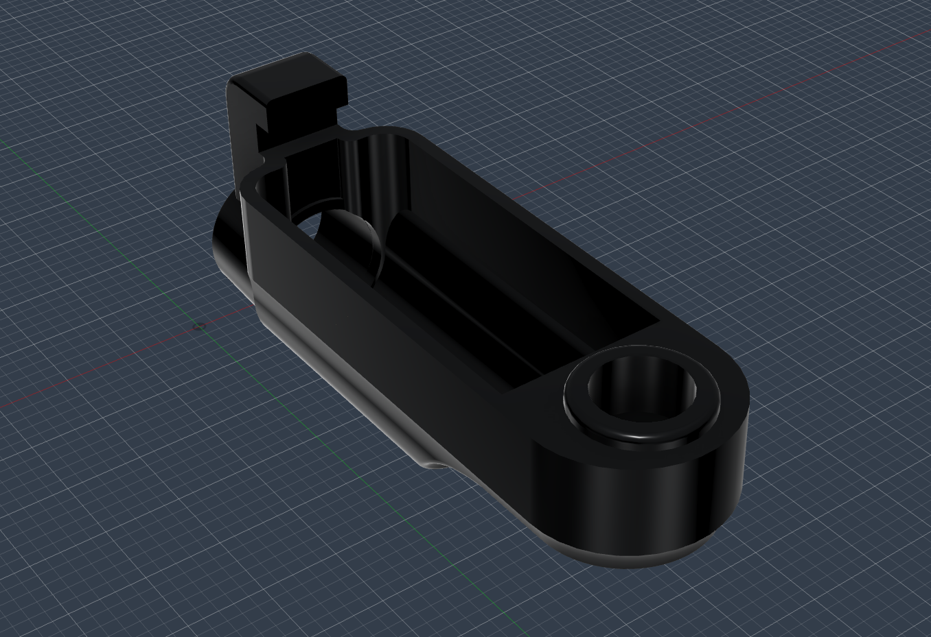
A difficult part I found was to correctly model the pogo pin placement. This is something I am still working on.
Thumb screw
I think that the thumb screw might be a M2,5 screw. 🥴 But I will have to either order or dig out some old screws to test. I think it is either M2 or M2,5.
I am also searching for the pogo pins, since the exact ones seem to be difficult for me to find…